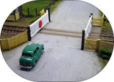
Level Crossing Gates
Here
is
a
way
of
constructing
working
model
railway
level
crossing
gates
where
a
minor
road
crosses
a
single
line.
Only
one
gate
is
provided
each
side
of
the
track
so
the
operation
involves
sequential
closure
of the gates.
The
gates
are
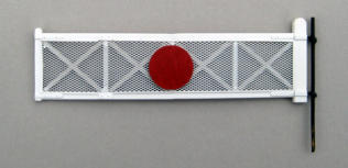
modified
Wills
gates
(4mm
scale)
covered
in
K&S
3/64”
Diamond
Special
Shapes
mesh
to
simulate
the
wire
netting
covering
of
the
gates.
A
brass
rod
is
fixed
to
the
stile
of
each
gate
by
means
of
soldered
pins
which
fit
through
two
holes
drilled
into
the
stile.
The
rod
is
a
push
fit
into
a
collar
on
the
motor gearbox final drive shaft underneath the baseboard.
Each
gate
is
driven
by
means
of
a
Multi
Ratio
Gearbox
sold
by
MFA/Como
Drills
(Part
917D)
which
offers
a
number
of
gear
ratios
by
which
the
speed
of
movement
of
the
gates
can
be
chosen
in
combination
with
a
variable
PWM
power
supply.
The
opposite
end
of
the
final
drive
shaft
is
provided
with
a
disc
having
a
peg
near
its
circumference.
The
rotational
movement
of
the
shaft
is
limited
to
90º
by
means
of
microswitches
contacted
by
the
peg
at
each
end
of
its
travel
in
conjunction
with
the
electronics
described below.
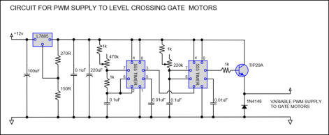
The
following
circuit
for
a
variable
PWM
supply
works
fine.
The
speed
of
movement
of
the
gates
is
adjusted
by
means
of
the
variable
resistors.
See
www.eleinmec.com/article.asp?28
for
more
information.
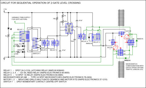
The
electronic
circuit
which
controls
the
sequential
movement
of
the
gates
is
shown
below.
The
control
panel
for
the
level
crossing
gates
consists
of
an
on-off
switch
(not
shown)
and
associated
LED
and
a
momentary
contact
DPDT
Switch
1
with
associated
green
and
red
LEDs
to
show
whether
the
gates
are
open or closed to traffic.
The
sequence
is
started
by
operation
of
the
momentary
contact
switch
1
which
(a)
activates
latching
relay
1
to
change
the
polarity
of
the
PWM
motor
supply
and
(b)
activates
either
relay
2
or
relay
3
to
trigger
the
555
timer.
The
output
from
pin
3
of
the
555
timer
activates
relay
4
to
close
the
motor
circuit
and
start
gate
motor
1.
The
output
pulse
is
long
enough
to
allow
the
motor
to
start
its
travel
and
release
microswitch
M1
which
switches
SPDT
relay
5
to
keep
power
to
the
gate
motor.
When
the
gate
motor
has
moved
the
gate
through
90º,
the
peg
on
the
circumference
of
the
disc
referred
to
above
switches
the
two
microswitches
M3
and
M4
to
cut
power
to
motor
1
and
start
motor
2.
Microswitches
M5
and
M6
are
then
released
ready
for
the
return
sequence
and
when
motor
2
reaches
the
end
of
its
travel
microswitch
M2
switches to operate SPDT relay 5 to cut power to the motor.
The
reverse
sequence
is
started
by
operation
of
the
momentary
contact
switch
in
the
opposite
direction
to reverse polarity of the PWM supply and activate the other of relay 2 and relay 3.
The
purpose
of
the
555
timer
is
to
provide
a
long
enough
pulse
to
allow
the
motor
to
start
its
sequence
and
release
the
microswitches
without
being
reliant
on
the
operator
keeping
the
DPDT
momentary
contact switch pressed for the required time.
Click or tap the image below for a short clip showing the operation of the gates.



© Richard Smith 2012-19. All rights reserved.





















Level Crossing Gates
Here
is
a
way
of
constructing
working
model
railway
level
crossing
gates
where
a
minor
road
crosses
a
single
line.
Only
one
gate
is
provided
each
side
of
the
track
so
the
operation
involves
sequential closure of the gates.
The
gates
are
modified
Wills
gates
(4mm
scale)
covered
in
K&S
3/64”
Diamond
Special
Shapes
mesh
to
simulate
the
wire
netting
covering
of
the
gates.
A
brass
rod
is
fixed
to
the
stile
of
each
gate
by
means
of
soldered
pins
which
fit
through
two
holes
drilled
into
the
stile.
The
rod
is
a
push
fit
into
a
collar
on
the
motor
gearbox
final drive shaft underneath the baseboard.
Each
gate
is
driven
by
means
of
a
Multi
Ratio
Gearbox
sold
by
MFA/Como
Drills
(Part
917D)
which
offers
a
number
of
gear
ratios
by
which
the
speed
of
movement
of
the
gates
can
be
chosen
in
combination
with
a
variable
PWM
power
supply.
The
opposite
end
of
the
final
drive
shaft
is
provided
with
a
disc
having
a
peg
near
its
circumference.
The
rotational
movement
of
the
shaft
is
limited
to
90º
by
means
of
microswitches
contacted
by
the
peg
at
each
end
of
its
travel
in
conjunction
with
the
electronics
described
below.
The
following
circuit
for
a
variable
PWM
supply
works
fine.
The
speed
of
movement
of
the
gates
is
adjusted
by
means
of
the
variable
resistors.
See
www.eleinmec.com/article.asp?28
for
more information.
The
electronic
circuit
which
controls
the
sequential
movement
of
the
gates
is
shown
below.
The
control
panel
for
the
level
crossing
gates
consists
of
an
on-off
switch
(not
shown)
and
associated
LED
and
a
momentary
contact
DPDT
Switch
1
with
associated
green
and
red
LEDs
to
show
whether
the
gates
are
open
or
closed
to
traffic.
The
sequence
is
started
by
operation
of
the
momentary
contact
switch
1
which
(a)
activates
latching
relay
1
to
change
the
polarity
of
the
PWM
motor
supply
and
(b)
activates
either
relay
2
or
relay
3
to
trigger
the
555
timer.
The
output
from
pin
3
of
the
555
timer
activates
relay
4
to
close
the
motor
circuit
and
start
gate
motor
1.
The
output
pulse
is
long
enough
to
allow
the
motor
to
start
its
travel
and
release
microswitch
M1
which
switches
SPDT
relay
5
to
keep
power
to
the
gate
motor.
When
the
gate
motor
has
moved
the
gate
through
90º,
the
peg
on
the
circumference
of
the
disc
referred
to
above
switches
the
two
microswitches
M3
and
M4
to
cut
power
to
motor
1
and
start
motor
2.
Microswitches
M5
and
M6
are
then
released
ready
for
the
return
sequence
and
when
motor
2
reaches
the
end
of
its
travel
microswitch
M2
switches
to
operate
SPDT relay 5 to cut power to the motor.
The
reverse
sequence
is
started
by
operation
of
the
momentary
contact
switch
in
the
opposite
direction
to
reverse
polarity
of
the
PWM supply and activate the other of relay 2 and relay 3.
The
purpose
of
the
555
timer
is
to
provide
a
long
enough
pulse
to
allow
the
motor
to
start
its
sequence
and
release
the
microswitches
without
being
reliant
on
the
operator
keeping
the
DPDT momentary contact switch pressed for the required time.
Tap
the
image
below
for
a
short
clip
showing
the
operation
of
the
gates.
© Richard Smith 2012-19. All rights reserved.